Fix it felix jr nes game download free. Larger amounts present rather expanding quantities of haphazardly set deterrents, for example, purple flower beds which keep Felix from bouncing up or down between two windows. The adaptations made accessible online likewise highlight open window screens for blocking Felix on a flat plane, while the arcade form rather has various vast heaps of blocks fall between two windowsills and stall out the beginning of the fifth round. Felix can bounce over these blocks helps to get over the column.

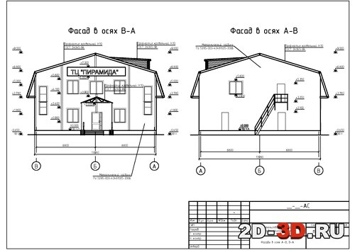
DWG is an independent firm of structural engineers, consultants and technical specialists that specialize in Efficient Engineering. The DWG file format is used in 3-dimensional drawing and design programs, such as AutoDesk AutoCAD. Using a vector-based graphics program, such as the commonly-used Adobe Illustrator, or a direct conversion program, you can convert a DWG file to Encapsulated PostScript (EPS).
Create 3D Inventor parts associative to the source 2D geometry created in AutoCAD. • Insert an AutoCAD DWG file as an associative DWG: • In a part file: • Manage tab Insert panel Import • 3D Model tab Create panel Import • In an assembly file: • Assemble tab Component panel Place • In the Place Component dialog box, select a DWG file and click Open. For more information see • In a 2D sketch, click a face or work plane to set the sketch plane. • Click Sketch tab Create panel Project DWG Geometry. • Select the geometry to project. Select one of 3 options: • Single geometry • Connected geometry: Closed loop and/or open loop. • Geometry block.

Note: You can project DWG geometry in another part that is also open for edit in an assembly. • When done, select Cancel or right-click and select OK. • On the 3D Model tab, extrude the DWG geometry and create 3D features as desired. • In an assembly file, you can use the Joint, Constrain, and Assemble commands to create relationships between a DWG underlay block and a part. You can work on DWG geometry in an assembly file at the same time as working on the same DWG geometry in a part file. When changes are made to projected DWG geometry in a part file, the corresponding DWG geometry in the assembly file is updated with these changes.
The projection associativity will be kept even when the DWG is modified. For example: • Insert a part (PART A) that has AutoCAD 2D geometry into an assembly and save the file. • In a new part file (PART B): Create a sketch and project the DWG geometry from PART A into PART B. The projection associativity will be kept even the DWG is modified. When the original DWG file is updated in AutoCAD, the corresponding Inventor files will be updated accordingly, either for geometry change or position change.